Low cost DIY Nest-style IoT thermostat project
DIY Nest-style thermostat project


Project outline
Over the last few years the world of connected devices has become accessible to the everyday amateur, with platforms like Arduino driving down costs to the point where even complex projects can be prototyped for a few pounds. When I first heard of the Nest thermostat, I began almost immediately to consider what a DIY version would look like. This page logs my thinking, research, and work on the final prototype.
Thinking
Once upon a time, most IoT boards were so large and unwieldy that the idea of making a small domestic device with one just didn't make sense. Traditionally, thermostats are discreet, low-profle devices, that blend into their environment. Normally attached to walls in a permanent location, they are usually only a couple of centimetres thick.
The existing thermostat in my home (Sunvic TLX 6501) was already a wireless device. It relied on a 433MHz radio link to trigger the relay attached to the boiler. The thermostat's functions were:
- Wireless transmission of start/stop triggers for boiler.
- Single analogue temperature sensor.
- 7 day timer with a variety of different programs which could be set for any day of the week.
- Backlit display allowing status display, program selection, set up and manual override.
- Seven buttons to allow user interaction.
All this was powered using two AA batteries, with a running time of several months before replacement.
My aim was to replicate as many of the existing functions as possible, with the addition of some form of network connectivity, to allow more advanced control, data analysis and debugging.
Research
Platform
I looked at all sorts of possible platforms. Arduino offer a huge range of possible form factors now, some of which would certainly fit the bill in terms of small form factor. However, adding connectivity to these boards always entails some additional hardware; wifi boards, bluetooth boards etc. which would increase the size and cost of the project. My attention soon shifted to ESP8266 boards. Again, there are a range of options here, with some excellent host boards exposing I/O and allowing simple USB-based programming, avoiding the need for additional programming boards. I ended up basing my thermostat on a Wemos D1 mini ESP8266 board which has a small form factor, good I/O and simple programming using the Arduino IDE. It also offers the possibility of over-the-air programming updates.
Sensors
The choice of sensors to attach to the microcontroller board was a fairly simple one, since I planned to use this board for a very specific purpose. Temperature detection was the absolute minimum requirement, but since the board has a single analogue input, the range of options was still wide. In the end I chose the well-documented and economical DHT-22 digital sensor, which provides temperature and humidity with reasonable accuracy, without needing additional circuitry or complex software.
In the future I intend to investigate a small PIR motion sensor, as well as additional environmental sensors such as air quality or light intensity. The board has enough I/O capacity to host several additional sensors when and if required.
Power
Initially this project will be powered from the mains using a small AC/DC wall adapter and a USB lead. Once the project is reliable, the intention is to investigate a completely wireless, rechargeable power supply.
Display
I looked into options such as LCD, LED and OLED. Whilst all are possible, for low cost and simple connectivity nothing beats the four pin monochrome OLED modules. They use two digital pins, are very low power, give a bright legible display at any angle, and cost a few pounds.
Housing
The housing is really a secondary concern, since the project could operate quite happily off a breadboard. However, in order to help me focus on producing something as close to a consumer product as I could, I decided to include the housing design in my initial thinking. All the components were chosen with the housing in mind.
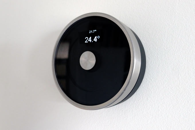
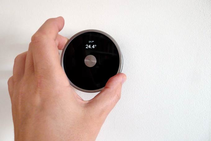
I decided to emulate the Nest user interface, using a simple rotation to make adjustments, which in turn emulates a traditional analogue thermostat. I also wanted to include a push button, and ideally wanted to have this unified with the rotary control.
Build

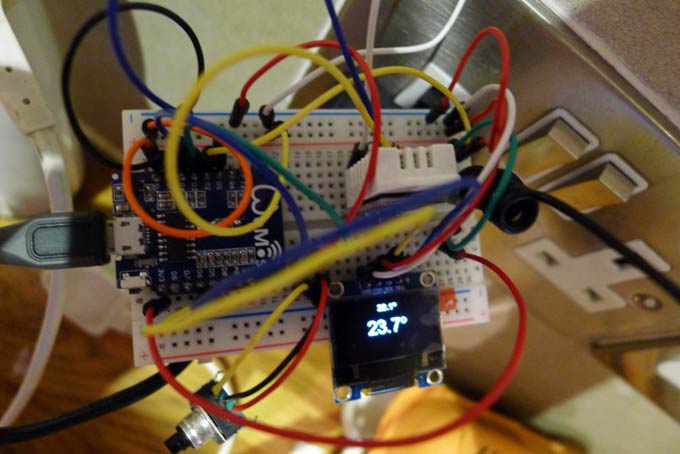
To start testing the basic setup, I first ordered the bare minimum of parts needed:
- Wemos D1 mini WiFi microcontroller
- DHT-22 digital temperature/humidity sensor
- 433MHz transmitter
- Breadboard and jumpers
Total cost: Approx £12
Once I had the parts wired together, I began to run some simple tests.
- First determine that I can run a simple sketch on the D1.
- Confirm that the D1 can read the DHT-22.
- Confirm that the D1 can connect to the local WiFi network and send basic data.
- Confirm that the D1 can send signals to the 433Mhz transmitter.
Signal analysis
The real challenge now began - to reverse engineer the specific coding used by the original Sunvic thermostat to transmit the on/off signal to the receiver connected to the boiler's relay. This was further complicated by the fact that the Sunvic contains a set of DIP switches that allow the transmitter and receiver to be coded to each other. I also needed to be sure that the signals were sent with the same interval.
To do this I tried various approaches, including scouring the net for previous research on this topic. When this turned up nothing, I decided I needed a receiver, to scan the 433MHz band for the signals. Luckily I had bought the transmitter as part of a matched pair, so I could hook up the receiver to the D1, and use a simple sketch to scan for signals. Unfortunately, it turns out this band is very noisy - there is a huge amount of local transmission on this frequency from toys, doorbells, remote controls and other thermostats in the building. So whilst I could see plenty of signals arriving, isolating and decoding just the signal for this specific device was a lot harder.
That led me to use a technique I have tried in the past for signal analysis: the sound card oscilloscope. When testing audio circuits, pulse generators or tachometers, I have hooked up my sound input to the signal via a simple probe, and recorded the output as an audio sample. So I applied the same technique with the 433MHz receiver, connecting the probe to the output. I could monitor the recording on-screen as a waveform, and by triggering the original thermostat, watch the signals arrive. Then it was simply a matter of analysis.
It turned out to be a simple pulse pattern made up of long and short pulses of specific lengths, with a longer pause, before the pattern was repeated several times (presumably to ensure the signal gets through in case of interference or weak signal). The OFF signal was a variation on the pattern, using the same building blocks. Changing the DIP switches altered the pattern of long short pulses for both ON and OFF signals.
Using an audio application (Audacity is perfectly capable) I could view the timing information of these pulses very precisely, and was able to measure their durations in microseconds. Although slightly variable, I managed to find a reliable average over a recording of several seconds' worth of pulses.
The thermostat transmitter also sends the current state signal once every minute, presumably as a keep alive, to ensure the receiver doesn't assume the transmitter has failed. So this too had to be reproduced by the DIY version.
It was then a matter of creating a sketch that could send this form of digital signal to the transmitter. After a few tests, monitored using the sound card oscilloscope, by varying the length of the pulses in microseconds within the sketch until the received signals matched the timings of the recorded originals precisely, I could reliably trigger the boiler relay from anywhere in the house, using the D1.
Logic
So I now had a microcontroller, with which I could communicate via WiFi, that could read the local temperature (and humidity), and could reliably control the remote relay on the boiler. The next step was to try and build some thermostat logic into the sketch.
TO BE CONTINUED...
